

Blog
The 2017 edition of the A117.1 Standard for Accessible and Usable Buildings and Facilities comes with the most significant spatial changes that we have seen in any recent code cycle.
The 2017 edition of the A117.1 Standard for Accessible and Usable Buildings and Facilities comes with the most significant spatial changes that we have seen in any recent code cycle. As more states and local governments adopt A117.1-2017 as the technical standard of reference under Chapter 11: Accessibility of the International Building Code, builders, developers, architects, and agencies, among others, will be faced with some big changes when it comes to accessibility requirements.
Many of the basic building block clearances that have remained relatively the same since the 1986 edition of the standard have been expanded based on the findings of The Wheeled Mobility Task Group (PDF), a study of mobility device users conducted by The Center for Inclusive Design and Environmental Access (IDeA) out of the University at Buffalo, SUNY.
What has changed and how will designs be affected? Here are our top 5 spatial changes in A117.1-2017 and the impact those changes could have on building design:
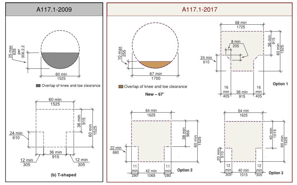
The turning circle is getting bigger, and the T-shaped turn is getting more complicated.
The first option is 68”x60” and has two 16”x24” portions removed from two corners with an 8”x8” chamfered interior corner. The second and third options are both 64”x60” with either 11”x22” or 12”x20” rectangles removed from two corners on one side. One arm or the base of each T-shaped turn option is permitted to overlap knee and toe clearance extending below an element.
Many rooms and spaces that require a turning space will need to increase in size to accommodate the enlarged dimensions. For example, toilet rooms will noticeably be impacted, especially due to the reduction in knee and toe clearance overlap permitted at all new turning space options. Expect larger Accessible Unit and Type A Unit bathrooms, as well as larger common use toilet and bathing rooms.
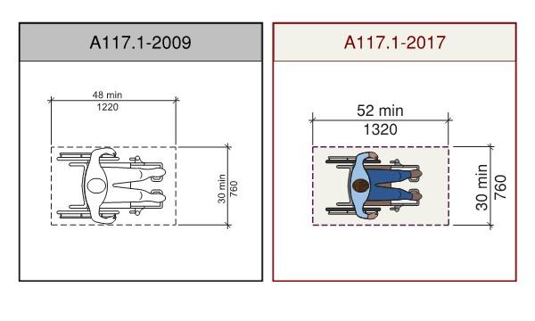
Previously, the dimensions for the clear floor space required at accessible elements was 30” in width and 48” in length. In A117.1-2017, the length of the clear floor space has increased to 52”.
Layouts at operable parts, plumbing fixtures, appliances, and other accessible elements may need to be adjusted to accommodate the increased length of the clear floor space.
For example, where a centered clear floor space is required at the range in a Type A unit kitchen, a minimum clearance of 26” is required between the centerline of the range and an adjacent countertop or appliance, increased from 24” under previous A117.1 editions.
Accessible routes throughout areas with furnishings, planting beds, outdoor kitchens, and other elements that can impact the clear width of the route must be positioned to provide a 48” clear width. Like interior routes, reductions in clear width along exterior accessible routes must be sufficiently spaced out to meet the 52” minimum clear length between obstructions.
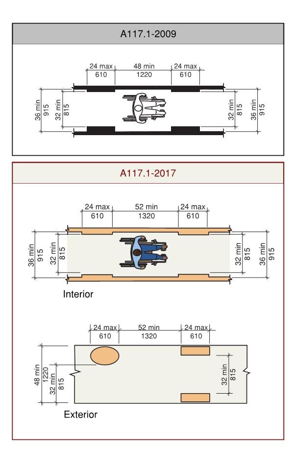
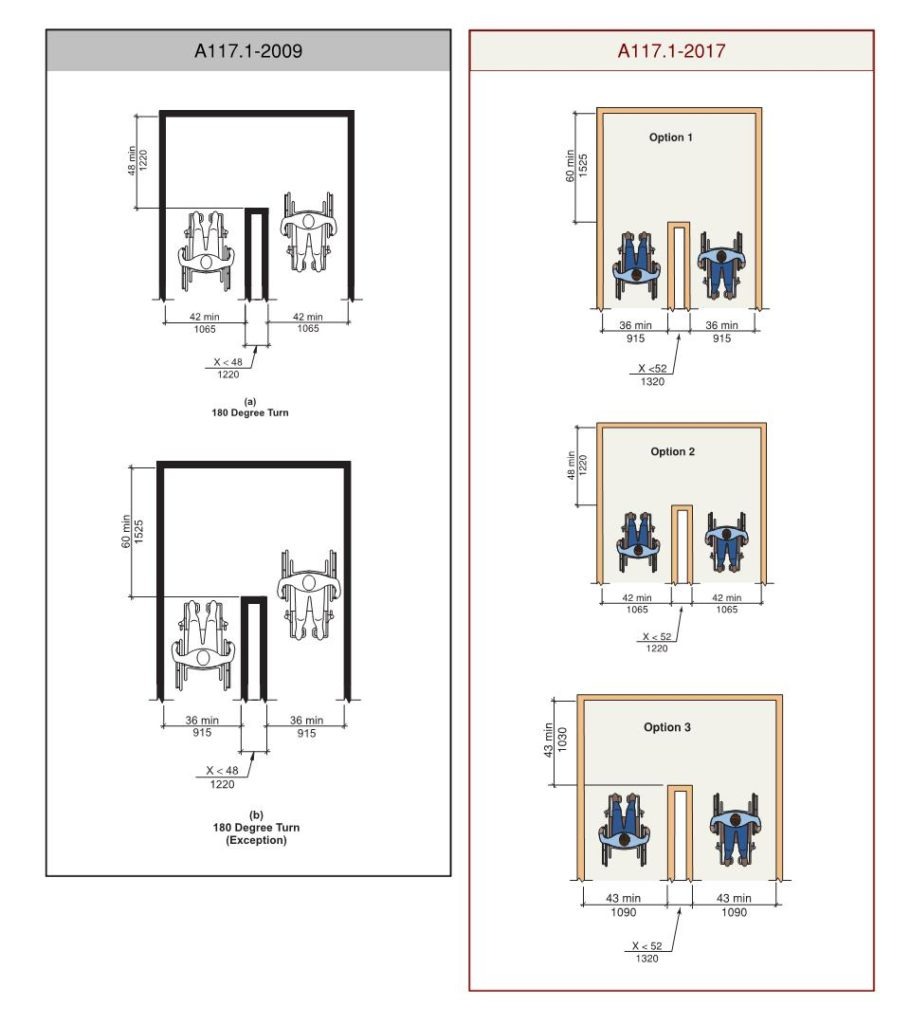
To accommodate a 180-degree turn without necessitating a clear route of more than 36” in width, a minimum distance of 52” must be provided between two 90-degree turns. This increase from 48” under A117.1-2009 to 52” under A117.1-2017 corresponds with the expansion of the clear floor space.
Where less than 60” is provided at the base of the turn, the width of the legs into and out of the turn must increase to correspond with the images below. Where each leg is a minimum of 42” in width, the base of the turn must be 48” minimum. Where each leg is 43” inches minimum in width, the base of the turn is permitted to be 43” minimum.
Shopping aisles at small stores and routes into and through multiuser restrooms will likely be impacted by these increased clearances. Mail rooms in multifamily residential buildings are also commonly subject to clearances for 180-degree turns, which will likely result in an increase in the footprint required to negotiate rows of mailboxes.
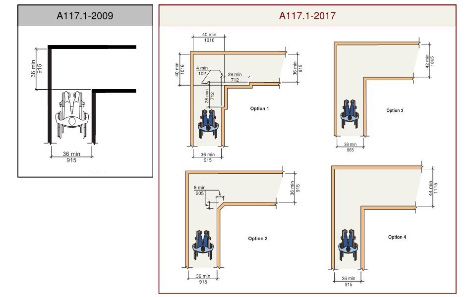
Previously, there were no additional spatial requirements for 90-degree turns. Under A117.1-2017 requirements, increased clearance is required to negotiate the turn. Four options are provided, as shown in the image below.
To maintain the 36” minimum width for both sides of the 90-degree turn, the interior corner must be chamfered, or the width of the route must increase to 40” minimum for a 28” minimum length on both sides of the interior corner.
Alternatively, a 36” wide route is permitted to turn 90 degrees into a 44” minimum wide route without additional clearance at the corner. A 38” wide route is permitted to turn 90 degrees into a 42” minimum wide route.
Like spaces requiring a 180-degree turn around an obstruction, accessible routes throughout compact spaces like multiuser restrooms and small stores, or larger rooms with fixed elements and furnishings will need to be designed to accommodate the increased clearances depicted in the images below. While older codes would require a 36” wide route to negotiate turns, now more care must be applied to layouts to ensure that one of the 90-degree turn options is provided.
Because these spatial changes are significant, alterations to existing buildings will still be permitted to utilize clearances that align with requirements in A117.1-2009. In the 2017 edition, the diagrams detailing those clearances are provided and identified for use in existing buildings and facilities only.
For projects subject to new construction criteria, designers will need to take these enlarged clearance requirements into account early in the design process to ensure that enough space is provided to accommodate the increased dimensions.
If you are working in a jurisdiction that has adopted the 2021 IBC and/or A117.1-2017 and are unsure how it will affect your project, our consultants are here to help. Click here to contact us.
Contributor: Theresa D’Andrea, Senior Accessibility Consultant
Peter Stratton